
Innovate | Collaborate | Succeed

About Us
NU Marine provides undergraduate students at The University of Newcastle the opportunity to cultivate cutting edge skills while developing autonomous platforms. NU Marine challenges students to apply their technical knowledge to exciting multidisciplinary projects and work as a team to produce a functional autonomous surface vessel. The team competes in the international Maritime RobotX Challenge, which alternates bienially between a physical competition and a virtual simulation. The team is competing in the 2022 Maritime RobotX Challenge to be held at the Sydney International Regatta Centre from the 11th to 17th of November.
Learn more about the Maritime RobotX Challenge here.
Meet the Team
-
![]()
Jack Humphreys
Computer Systems Engineering and Science
Operator Control Station
-
![]()
Joshua Baker
TEAM LEADER
Mechatronics Engineering
-
![]()
Jay Gates
CHIEF ENGINEER
Mechatronics Engineering
-
![]()
Alec Mowbray
Mechanical and Mechatronics Engineering
-
![]()
Daniel Keen
Electrical and Mechatronics Engineering


The team in action
NU Marine have been hard at work in 2022, take a look at a some of what they’ve been up to and meet the team along the way!
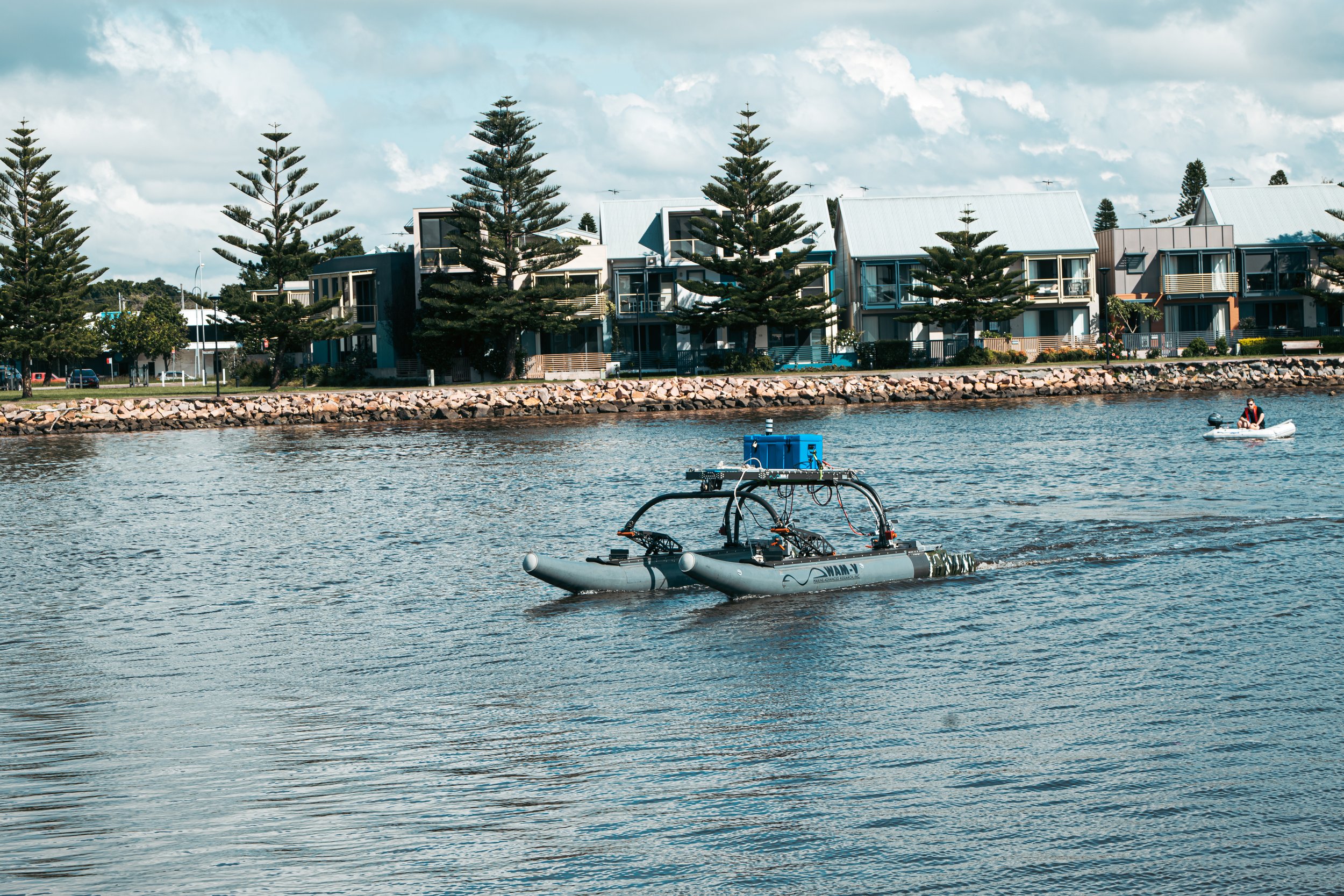
NU Marine WAM-V Model
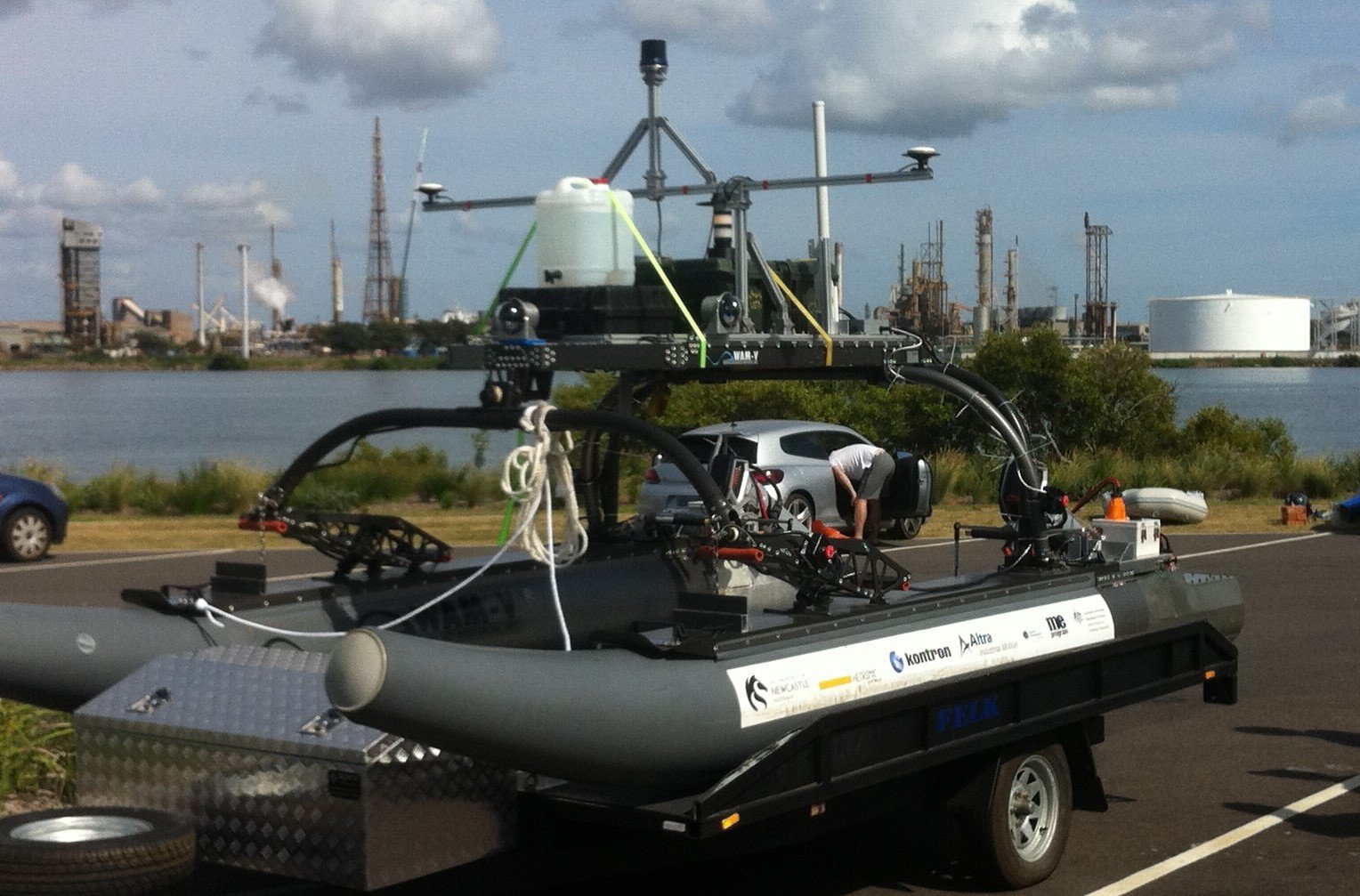
The Wave Adaptive Modular Vessel (WAM-V) serves as an excellent foundational platform off which autonomy can be built. NU Marine has looked to leverage off the WAM-V’s unique platform structure to maximise the hardware capabilities of the vessel. The model for team’s current hardware configuration can be seen below.
Navigation System
The navigation system has the role of informing the team of the position of the vessel, as well as what the surrounding environment looks like. It integrates the available sensors, in this case a LiDAR and GPS/IMU, and uses the incoming data from these measurements to estimate the state of the WAM-V and the world around it. An Unscented Kalman Filter (UKF) is used to manage the measurement updates and merge these with the mathematical process model that explains how the WAM-V should move. The UKF works by representing measurements and the state of the vessel as Gaussian probability distributions with varying mean and covariance. It has three main steps: first, obtain the measurements, then integrate these measurements to update the probability of the state using conditional probability, and last, predict the next state of the vessel. The fundamental process happening inside the UKF is called an unscented transform. Here, sigma points are formed around the mean of the input, and these are pushed through their respective non-linear function. The mean of the covariance of each of these sigma point outputs is taken and turned into the resultant probability distribution. The navigation system, with the help of the UKF, can then pass on estimates of state and landmark positions in the world to the other systems for use in their algorithms.

Plotted points returned by the Hesai Pandar-XT32
Vision System
The goal of the vision system is to use the input from the vessel's attached camera systems in order to identify and help locate different objects in the world, providing crucial knowledge to the system which will allow it to complete many of the competition tasks. The vision model utilises a CNN model known as YOLOv5, an extremely well optimised model used within many machine vision applications. The model has been trained on a collection of images and has been continually expanded upon as time has gone on, with approximately 3000 images making up the current training dataset. In the current configuration, images are read in from each camera at a fixed frequency and processed on a NVIDIA Jetson Nano. Each image is run through the detection model and the location of the proceeding bounding boxes for each object are recorded. The image is then split into 10 segments, with the segment each detected object appears in also being recorded. The purpose of this process is to provide as much information as possible to the Navigation system in order for the LiDAR to locate the detected objects and generate accurate range measurements, allowing for a map of important landmarks to be generated and for a path to be calculated.
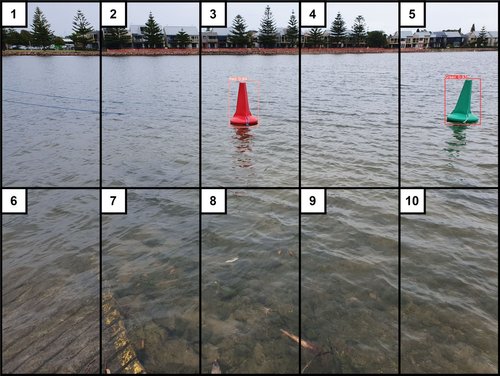
Vision system's processing of incoming images into segments
Power Management System
To power the platforms main hardware, sixteen 100 AH 3.4V Lithium Iron Manganese Phosphate (LiFeMnPO4) cells with a bespoke Battery Management System (BMS) were used. This bank of cells are split up into 2 parallel pairs with 8 cells in each for a nominal voltage of 26.4V. LiFeMnPO4 was chosen due to their durable, safe and reliable operation while in the wide range of operational environments needed. The BMS incorporates custom made voltage and temperature monitoring circuits for each cell, current sensing and a complete active balancing array with internal charging current sensing. The BMS uses multiple high-end micro controllers to collate, filter and transmit the data to the rest systems integrated on the platform. To achieve accurate active balancing, system identification was conducted to calculate the Open Circuit Voltage (OCV) and the total capacity of each cell. This data is also used to estimate a SOC using a 2 pair RC parallel pair equivalent circuit. A battery shore monitoring system was created to monitor graphs in real time of temperature, SOC, and cell voltage while the WAM-V is in operation.
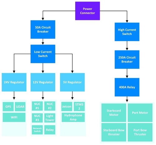
Layout of power system components
Supervisory System
The supervisory system acts as the brain of the platform. It is responsible for being the translator between the OCS and the ROS network on the boat. Distributing messages to and from ROS nodes and ensuring each system has the information that it requires. The supervisory system is also responsible for flagging and acting on any faults detected on the WAM-V. Another aspect of the supervisory system is the mission planning algorithm. The version deployed on the WAM-V takes an input from the OCS specifying what task the platform should be attempting to execute, and with this information, interprets feature positions from the navigation node to develop a mission plan, and pass waypoints to the guidance node. The mission planning suite is also responsible for resource management and will return to base if it cannot execute the designated task for any reason, such as a depleted battery.
Guidance System
The guidance system is responsible for generating a state trajectory which can meet the mission requirements communicated by the supervisory system and can be feasibly achieved by the control system. The guidance solution takes both the binary occupancy grid map and the mission planning data as inputs, generated by the navigation and supervisory systems, respectively. This data is used to generate a collisionfree trajectory from the current pose to the mission goal via the D* Lite path planning algorithm, which is a dynamic variation of the widely implemented A* algorithm. Each obstacle is inflated by a fixed radius to ensure the WAM-V remains a conservative distance away from objects on the course. Key way points are then extracted from the algorithm's path result and fed into a quadratic programming routine which fits optimally smooth cubic splines to the path. The quadratic programming spline generation ensures the reference trajectory is smooth and continuous, and as such can be reasonably tracked by the control system. This process is run in real time and continually updates the path during active missions based on changes in the map environment.
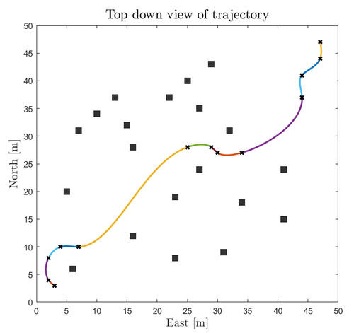
Top down view of the optimised state trajectory produced by the quadratic programming solver
Propulsion System
The control solution's purpose is to accurately and efficiently navigate the unmanned surface vessel (USV) along a desired path. To accomplish this, two control schemes were developed for trajectory tracking and station keeping tasks. The trajectory tracking controller uses two separate feedback control loops to maintain body fixed velocity and earth fixed heading of the boat. Both control loops use proportional integral derivative (PID) with static gains and an anti-integral windup to perform effective tracking of the USV. The station keeping controller uses three separate PID control loops to effectively maintain the pose of the USV. Through the thrust configuration on the boat, the USV can maintain the heading and position on the water with external currents and wind imposing disturbances on the system. The three separate control loops track the local earth fixed x and y positions along with the earth fixed heading and by using the thruster configuration an appropriate thrust output can be determined. The current position, heading and velocity is received from navigation along with the desired position, heading and velocity for the planned path from guidance to correctly determine the given errors for the PID control loops. Both controllers were tested within simulations to confirm their feasibility. A nonlinear model predictive controller (NMPC) was also simulated effectively for trajectory tracking a planned path but due to limitations of having accurate models of the WAM-V and thrust profiles of the Torqeedo motors, this was simplified to this current model-free solution. With sufficient system identification of the vessel and motors, a solution would be able to be produced.
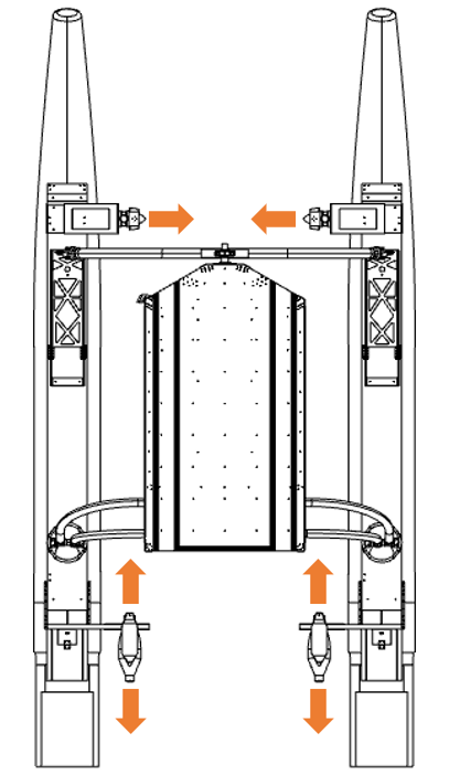
T thrust design configuration used for vessel actuation
Operator Control System
An Operator Control Station (OCS) was developed to communicate with the vessel from the shore. This device houses a Raspberry Pi 4 attached to a LED Panel which allows for clean interfacing to and from the vessel via a user interface. The bridge between the OCS and the WAM-V itself is created using a pair of Ubiquity Rocket 5AC Lite base stations linked together in point-to-point mode, essentially acting as an invisible Ethernet cable. The OCS serves 3 main purposes:
- To relay and display important information to the team such as GPS outputs, useful plots and even more useful error messages.
- To inform the vessel of whether it should be behaving in manual or automatic configuration and to facilitate this through either manual input commands from an attached PS4 controller or through competition task and waypoint inputs which dictate the behaviour of the onboard autonomy systems.
- To provide remote E-Stop functionality, allowing the team to cut power to the motors from the shore.
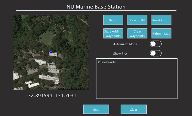
Early version of the team's Operator Control System interface
Safety System
To both comply with competition regulation and uphold the highest degree of safety, a designated safety system has been developed. Attached to the vessel are 4 E-Stop switches that are connected to a shared relay. If one of these buttons is pressed, a further relay is tripped, blocking power flow to the motors and adjusting the status light atop the boat accordingly. Furthermore, connected to E-Stop relay is an STM32H7 microcontroller, this board is configured to receive in serial data from the OCS on the shore through a link created between a pair of RFD900x devices. Within the OCS housing, a separate STM32F303 is set up to read in a signal from a fifth E-Stop button, mounted to the housing. If this button is pressed, a signal is sent across the serial link in under a second, triggering the relay and mimicking the effect of pressing a button mounted to the vessel itself. In addition to this functionality, a consistent frequency “heartbeat” message is sent across the serial link. If this message is not received by the vessel for any reason, power is also cut to the motors, maintaining safe operation of the vessel.
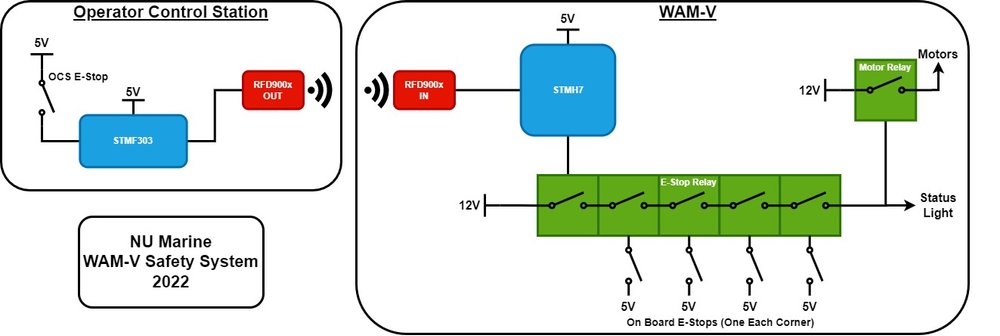
Visualisation of the safety system architecture
Source: BJCP Style Guidelines
For further information, please see NU Marine’s Technical Design Paper for 2022.
Documentation of Design Decisions


Team History and Progress
The University of Newcastle has participated in the RobotX Competition since its’ inception in 2014. NU Marine will attend it’s fourth RobotX competition in 2022, after competing in Singapore (2014) and Hawaii (2016, 2018). The team has continually evolved throughout the years, and as such so have the hardware and software design decisions. NU Marine has persevered through the challenging dynamics imposed by the COVID-19 pandemic. The 2022 team is looking to create a well-documented knowledge base that will serve as a foundation for future years to come. The team is looking to increase the involvement of younger members and facilitate a comprehensive knowledge transfer between yearly team cycles.

Singapore (2014)
Hawaii (2018)

Hawaii (2016)
NU Marine 2022 Sponsors
NU Marine has been fortunate to have the support of the following sponsors in 2022.


